The following is a collection of product testing inquiries that helps product and system manufacturers seeking to get their products approved for use in the High Velocity Hurricane Zone (HVHZ). This information is also intended to help the test laboratories perform the testing in compliance with the HVHZ.
- Soffits do not have to pass the impact test.
- The air infiltration tests must be performed before the water infiltration test.
- The structural load test, for products that are required to be mounted on CBS block, can be performed on a wooden buck when the product is impact resistant. Else, it needs to be tested on CBS.
- In lieu of testing all the applicable cases (of variations in size and mounting locations), comparative analysis may be allowed, provided three specimens are tested to positive failure, and three specimens are tested to negative failure.
- From the three tests, in the direction which proves weakest, curves are derived.
- If the ultimate load for any of the three specimens tested varies more than 20% from the average, three additional tests shall be made and all tests considered in determining the average ultimate load.
- An average of the three curves is then taken. Two points on the curve are chosen, for which two additional specimens are to be tested to prove these points. The results from these last two tests are to be within the 20% margin previously mentioned to accept the comparative analysis for that product. This procedure applies only to shutters.
- All products tested under the fatigue loading sequence do not have to have a recovery of at least 90%. This only applies to cladding.
- The 2-mil polyethylene may not be substituted for a thicker one -- 2-mil polyethylene film must be used all the time. You may "only" use 4 mil when pressures exceed 150 psf.
- When testing the three required specimens and a failure occurs in the last specimen, you do not have to re-test three new specimens. An additional fourth specimen in the same conditions as the one that failed is allowed. If the specimen failed in impact, the fourth specimen tested must be the same and the impact locations are in the same locations as the one that failed.
- If the fourth fails, a fifth specimen will only be allowed if the specimen is changed (e.g. the anchoring spacing, the mounting for that condition, or extrusion for that particular mount). As a result, if the product fails on a mounting condition and all the mountings are the same you are allowed only a fourth specimen.
- If you have different mountings and one fails, it can be re-tested with a fourth specimen, and then a fifth if that mount is changed or modified.
- For glazed products failing in the glazed section, a fourth specimen is all that will be allowed; if you change the glass a new set of three would have to be tested.
- Three specimens are required to pass.
- Un-supported (free jambs) vertical members must comply with FBC section 1613.1 (5) for deflection requirements and must not exceed the allowable stress for the type of material used.
- The maximum end gap allowed between un-supported jamb and substrate cannot be specified as unlimited. The end gap must be limited either as tested or by the sealant (caulking) manufacturer's joint performance capabilities and recommendations. Design consideration must also be given to weathering, water proofing, fire propagation, material expansion, compatibility, working joints and sealant performance.
- Soffits do not have to pass the impact test.
- If you or the lab do not notify Miami-Dade County of the test seven days prior, your test is not valid, and your tests will not be accepted.
- The approved engineer listed with the certified testing laboratory must be present during the execution of a given test. If the listed engineer is not present during the test, that test shall not be accepted.
- A group of manufacturers of a particular product can get together with the purpose of testing for approval. A request for such testing must be made to the Department of Regulatory and Economic Resources prior to the testing (use the special project / hourly rate application). The intent of this procedure is to try to help manufacturers of the same products curtail the cost of testing.
- A Certified testing laboratory's report shall not be older than six months at the time it is submitted for product approval.
- If the laboratory testing the product does not have the capabilities to perform the metallurgical test, the laboratory is responsible to contract a Miami-Dade County Approved laboratory that can perform the test. The lab is to send the product for metallurgical testing; not the product manufacturer. The metallurgical laboratory must reference the product test number in the metallurgical test report.
- If you or the lab do not notify Miami-Dade County of the test seven days prior, your test is not valid, and your tests will not be accepted.
- The large missile cannon can be fired at a vertical angle to compensate for the missile drop causing a perpendicular impact to the specimen. The front of the barrel can be shimmed to cause a perpendicular impact to the specimen.
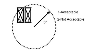
- A 5-inch radius circle in which the large missile can impact for all the specified locations of impact, is not allowed. The impacts that clearly state to hit the “meeting rail,” “joint” or “valley” must impact in those locations. A 5-inch radius must not be used in those impacts.
- The 5-inch radius mentioned in the South Florida Building Code section 2315.1(e) was established as a tolerance. The referenced section clearly states that the missile is to impact within the described circle. Should a missile fail to impact the sample “within” the prescribed circle, the shot will not be accepted, and the shot is to be repeated.
- The following are acceptable and unacceptable shots depicted as 1 and 2, respectively. Locations specified for impact such as but not limited to meeting rails, mullions, valleys and seams do not have an established tolerance. Therefore, the specified location is to be impacted.
- The large missile cannon can be fired at a vertical angle to compensate for the missile drop causing a perpendicular impact to the specimen. The front of the barrel can be shimmed to cause a perpendicular impact to the specimen.
A specimen will fail the testing if the small missile goes through.
The small missile test is required:
- When prior to the large missile impact the specimen has an opening that a 3/16" sphere can pass, and this opening is perpendicular to the trajectory of the missiles being shot. Also, it is required for products to be installed above 30 feet in elevation and are not to require any protection device.
- All 10 small missiles must be fired at once at the required speed for which only the speed of one has to be measured.
After the large missile test
- The small missile test is performed on the same specimen as used in the large missile test.
- The small missiles are aimed at the same area as where the large missile impacted; this being the center of the specimen and 6 inches from one corner. Also, Ordinance 93-141 requires a third small missile impact “distributed uniformly over a two square foot area located at the center of the long dimension of the specimen near the edge.”
- When performing a static loading per TAS202-94 and a plastic filament is needed for air leakage, you can load the specimen to +0.5 test & release, then +1.0 test & release, and then -0.5 test & release, then -1.0 test & release provided all necessary measurements are recorded.
- The sequence for testing TAS202-94 when loading the specimen is to first run the required “positive” design pressures and then the "negative" design pressures.
- In Protocol TAS202, if the product is impact resistant (TAS201 & TAS203 will be performed). One specimen to TAS202 is allowed. If the product is non-impact, three units are required.
- When the forced entry test is required and you are not testing for impact, all three specimens tested for protocol TAS202 must undergo the forced entry test.
- The sequence of testing for products that must meet the water requirements of protocol TAS202 is first, test the air infiltration. Second, load the product to 0.5 x test load. Third, load to design pressure. Fourth, test the water at its corresponding pressure. Lastly, test to full test load.
- Deflection Measurements are to be taken on a sample at locations where the maximum deflection occurs. This may differ from product to product. If a sample's deflection is measured at a point where there is another point deflecting more, an additional dial indicator shall be placed at that new location.
- If a failure occurs in any of the various test procedures of the TAS202 protocol, the entire sequence of testing needs to be repeated on a new or revamped sample. If the specimen fails to meet any of the procedures within TAS202, the specimen has failed said protocol.
- When performing a static loading per TAS202-94 and a plastic filament is needed for air leakage, you can load the specimen to +0.5 test & release, then +1.0 test & release, and then -0.5 test & release, then -1.0 test & release provided all necessary measurements are recorded.
- The specified dimensions and type of wooden 2x4 required for the large missile impact test in Protocol TAS201 shall be as specified in PA201 section 6.3.2.1 (No. 2 Southern Yellow Pine S4S). The length shall be not less than 6 feet and shall not exceed 8 feet.
- The 3/16" opening criteria specified in TAS201-94 Section 6.3.2.3 applies to products that in their original state have openings of this dimension prior to being impacted by the large missile test. This criterion is for products that have a 3/16" opening perpendicular to the missile's trajectory. For example, a mesh-like shutter device, etc.
Numbers of anchors required
Anchors are qualified based on mounting condition into substrate tested and verified by calculations. Anchor manufacture may apply for component approval of the brand and type anchor tested.
Adding additional anchors to an existing Product Approved product
You must submit for a revision of your product to include the additional anchoring devices.
Component approval for anchors
The process for obtaining the component approval for anchors requires testing per ACI 355-2-07. See anchor checklist.
- A wood screw or sheet metal screw tested in wood under shear conditions can be substituted with a self taping concrete anchor of the same or greater root diameter, provided the engineer has listed said anchor in the approval document and said anchor has a current NOA or published literature for the anchor.
Anchor spacing calculations
The allowable load, based on the fastener's/anchor's safety factor, shall not be exceeded when calculating anchor spacing on submittals compared to the units tested. This is the reason for requiring anchor calculations for most products. These calculations are not to be misinterpreted with rational analysis on anchors. The calculations are as verification to assure that the load tested has not transferred a load to an anchor that exceeds its rated value.
- The spacing of anchors of a tested unit cannot be altered when the approval documents are prepared. The maximum spacing allowed in the approval documents will be limited to the smallest spacing between anchors used in the test. Load verification of anchors shall be based on the largest anchor load transferred in the tested unit.
Comparative analysis procedure
The only comparative analysis allowed on fasteners/anchors is when the specimen is tested on CBS block. Since this substrate has been determined to be the worst case application, comparative analysis is allowed to qualify approved anchors on concrete, metal, and wood.
Second, the fasteners/anchors submitted with comparative analysis shall not exceed the spacing at which the system was tested. This is due to the system's performance with the amount of fastening points on the original test. Spacing the fastening points further apart shall be verified with a test.
Third, this procedure applies to products that are impact resistant and non-impact resistant.
Comparative analysis cannot be performed to qualify larger fastener/anchor spacing for loads other than tested.
Pursuant to section 1715.5.2.2, 1715.5.4 and 2411.3.2.5 (5) fastener and anchor submitted with comparative analysis shall not exceed the spacing or the concentrated load at which the system was tested. This is due to system's performance with the amount of fastening point on the original test.
- By testing the largest door, you can get approval for all smaller doors of the same type for the same maximum tested pressure.
- For a door line that varies only in the size of glazing infill, you do not have to test all the different styles. You may just test the largest door with the largest glazing infill, and get approval for equivalent and smaller doors with proportionally equivalent or smaller glazing infills.
- If you test a double door application, you can get approval for a single door application without testing the single door, provided the double door system consisted of an inactive door leaf. Single door shall contain all component of active leaf of the double doors.
- If you want approval for door applications with side-lites and transoms, they have to be tested with both in place.
- Doors with glazing require multiple impact tests. Referencing the ordinance, section 2315.1 (e)(2)(aa) states that two impacts shall be to the glass and two other impacts through the thinnest section of the assembly which is not glass shall be performed.
- Roof access hatches (doors) are exempted for impact & cyclic requirements per section 1626.1 of FBC; however the structural uniform test loading shall conducted per SK-I.
Revolving entrance glass door questions
Learn the tests and the FBC code requirements to qualify revolving entrance doors.
Sliding glass door test requirements
If you want your approval to read "Approved for 3 panels or less," then test 3 panels, measure permanent set and if testing for impact, aim the projectile where specified below.
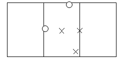
If you want your approval to read "Approved for 4 panels or less," then test 4 panels, measure permanent set and if testing for impact, aim the projectile where specified below.
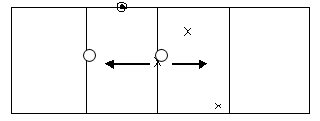
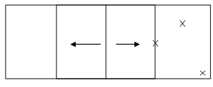
If you want your approval to read "Approved for multi-panels," then test six panels, measure permanent set and if testing for impact, aim the projectile where specified below.


Impact locations for double swinging glass doors
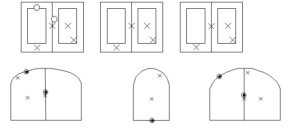
For double swinging glazed doors the following impact and permanent set diagram applies.
Water test requirement for entrance doors with flat sills
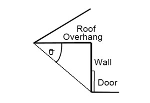
The water test on this particular product is only required when the roof's overhang is shorter than the height of the wall where the door is located. (If angle theta is greater than 45° then the water test is required on doors with flat sills.) This also applies to residential applications.
Testing panel doors for approval of the most combinations
- For three swinging panel doors, by testing the OXX configuration, we can accept O, X, OO, XX, XO, OOO, OXX, OOX, OXO.
- For four swinging panel doors, by testing one unit in an OXXX configuration and two units in an XX configuration, all to the same design pressure and same panel size, we can accept all possible four or less panel configurations. When testing TAS202 on the OXXX specimen place additional deflection gauges at mid-span of each of the two mulls; the first between the active and fixed panels, and the other at the right active-active panels. If comparative analysis is performed, the analysis must also address the mullion. Note that impact resistant units are also to be impacted at mid span of the mull, and are further limited by maximum cyclic pressure.
- For SGD panel doors, by testing 2-tracks and 3-tracks will qualify multi-track options. By testing regular jamb condition at one end pocket at other end will qualify multi jamb conditions.
During a large missile test if a rupture of 3/16 inch occurs, the specimen failed the large missile test because rupture of dimensions greater than 1/16" by 5" constitutes a failure per Ordinance 93-141.
- Garage doors with vents that have openings larger than 3/16" do not have to be tested for small missile impact.
- Garage doors have to be cycled in both positive and negative directions.
- When testing roll garage doors, the size specimen tested shall match the largest size sought for approval foresees installing or wants product approval.
- Small ventilators less than 60in2 can be installed on garage doors without undergoing the impact test requirements. Any larger vents will have to be tested with the door.
- After testing a garage door that has 2' tall panels at 8' high, approval for taller doors (10', 12' and 14') can be obtained only if the design of the door does not incorporate vertical supporting members.
- A removable beam behind the garage door for the needed structural support will be allowed as meeting the intent of permanently attached if a cable is attached from the beam to the door.
- You may test a full garage door without a glazed panel and cycle it 671 times. You then may test a "single glazed panel" for the 9,000 cycles and use it in the "whole" door system.
- Approval of Roll-up and Sectional doors is limited to three times the height of the door tested. This is only applicable when the tested door does not have the top or bottom ends restricted. If the tested door has locks that engage on the floor, or vertical reinforcements, this does not apply; in this case the door shall be approved for the height tested.
Chambers for garage doors
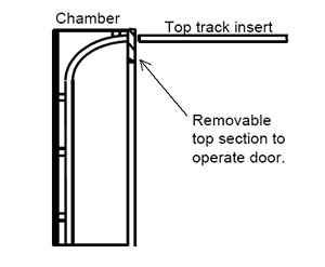
In order for the garage door to slide on after testing, the chamber should have sufficient depth to contain the curve portion of the track. A removable opening can be used at the top rear of the chamber where the top tracks can be installed after testing to roll the door up and down. See figure below.
Overhead garage door impact locations
- The impact locations for overhead garage doors without struts are the same as for shutters but rotated by 90 degrees; see question SH13.
- The impact locations for overhead garage doors with vertical struts, the impacts are as shown below.

Roll-up garage door impact locations
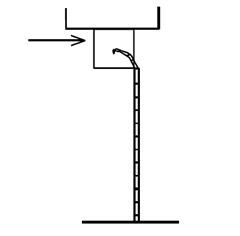
For roll-up garage doors only the center and a corner are required, but if the application is as shown below where the slats do not push up against the entire opening the roll drum must also be impacted.
Submitting garage door variations
- Only one design (material or pattern) is accepted per application.
- You may submit two different thickness' of the same design under one application by testing the thinner material. The approval of the thicker material will be based on the results of the thinner material tested.
- You may submit two different spans of the same design under one application by testing the longest span. The approval of the short span will be based on the results of the longest span tested.
- Each set of uniform static air test (TAS202), performed on a specific model, series or type of door requires one application.
- If a group of doors of the same design, material and pattern are being tested, it is only necessary to impact (TAS201) and cycle (TAS203) the thinner (weakest) door with the highest pressure. The satisfactory result of these tests will qualify the group of doors of the same design, material and pattern.
Procedure for testing garage doors to TAS202
- Apply 5 percent test load to remove the "play" of the door. Return pressure to 0 and set all deflections dials to 0.
- Bring pressure to 1/2 test load and record deflection.
- Remove all loads and read deformation if any. Recovery at this point shall be 95-100 percent.
- Bring pressure to test load and record deflection.
- Remove all load and record deformation permanent set). Recovery shall be at least 80 percent. Repeat the above in the negative direction in the same manner. Perform this test on as many samples required. The door shall be raised to an open position after the test. The laboratory must report if the door was operable or not after the test.
Procedure for reporting and installing garage door specimens to the test chamber
To begin with, only those anchors and fasteners that were tested shall be approved.
For Roll-Up Doors:
Specimen 1 test to TAS201 & TAS203 on 2000 psi concrete column on both sides and qualify two types of anchors.
Specimen 2 test to TAS201 & TAS203 on A36 steel column on both sides and qualify two types of fasteners.
Specimen 3 test to TAS201 & TAS203 on C-90 masonry block with 2000 psi grout column on both sides and qualify two types of anchors.
For Sectional Doors:
Specimen 1 test to TAS201 & TAS203 on 2"x6" or larger PT#3 Southern Pine wood buck on both sides and qualify two types of anchors.
Specimen 2 test to TAS201 & TAS203 on C-90 masonry block with 2000 psi grout column on both sides and qualify two types of anchors.
Specimen 3 test to TAS201 & TAS203 on 2000 psi concrete column on both sides and qualify two types of anchors.
In both cases mentioned above, each test will qualify one structural substrate application and two types of fasteners/anchors. Other types of substrates may require additional testing.
When down sizing any of the mentioned doors, the spacing of the anchors shall never exceed that which was tested.
The requirements of TAS202 can be performed in any type of substrate mentioned above and with any of the fasteners/anchors used for TAS201 & TAS203.
The test report shall describe the anchor/fastener type, location, embedment, spacing, type of column substrate and specification, etc. Calculations verifying the anchor/fastener used and recommended method of installing 2'x6" or larger buck to concrete/masonry block shall be submitted.
Please note that if you wish to only receive approval for one column substrate, then the three required tests for TAS201 and TAS203 shall be performed on that substrate. You may still qualify different anchors/fasteners on said column substrate.
Comparative analysis cannot be included on one Notice of Acceptance (NOA) for impact and non-impact glazed products. Non-impact resistant products and impact resistant products must obtain separate Notice of Acceptance (NOA).
- Comparative analysis can be performed on an impact resistant glazed product. Comparative analysis can be performed by conforming to the provisions in the Florida Building Code Section 2411.3.2.5 or 2411.3.2.6 as applicable.
Report the composition description of the material used in the glazing (impact resistant glass)
The following are some acceptable ways:
- From the three required impact and cycle samples, you can provide a different manufacturer's glazing into each of the samples.
The procedure followed is that the lower design pressure qualified from the three is what will be reflected on the approval. If one of the three specimens should fail the tests, three specimens of that type of glazing are to be tested to qualify that glass on the given system.
The determination of which unit or units are to undergo TAS202 testing will depend on the variations of glass type and thickness.
Determination and evaluation of a planned test procedure should be presented to BCCO in the form of a proposal.
- If you already have a Notice of Acceptance and you wish to qualify a different impact resistant glazing, you are required to show three samples passing the complete set of TAS201 and TAS203 testing, and testing to TAS202 will depend on the variations of glass type and thickness. You can take advantage in this type of testing by following case #1 above.
Acceptable ways of qualifying different glass-type manufacturers into a glazed impact-resistant product Notice of Acceptance
The following are some acceptable ways:
- From the three required impact and cycle samples, you can provide a different manufacturer's glazing into each of the samples.
- The procedure followed is that the lower design pressure qualified from the three is what will be reflected on the approval. If one of the three specimens should fail the tests, three specimens of that type of glazing are to be tested to qualify that glass on the given system.
- The determination of which unit or units are to undergo TAS202 testing will depend on the variations of glass type and thickness.
- Determination and evaluation of a planned test procedure should be presented to BCCO in the form of a proposal.
- If you already have a Notice of Acceptance and you wish to qualify a different impact resistant glazing, you are required to show three samples passing the complete set of TAS201 and TAS203 testing, and testing to TAS202 will depend on the variations of glass type and thickness. You can take advantage in this type of testing by following case #1 above.
Different levels of reinforcement in the testing of glazed products
The approach is to determine the largest level of reinforcement, which typically corresponds to the highest pressure for the system. Arrange the units in decreasing level of reinforcement and projected/applicable design pressure.
If non-impact resistant, the following applies:
Test three units of the highest level of reinforcement to the highest design pressure for the system as required in TAS202. These units are to undergo all of the requirements of TAS202. Then test one additional sample for each decreased level of reinforcement and to the corresponding determined design pressure. Each of these additional specimens is to be tested to the structural requirements of TAS202, and depending if other parts of the system are decreased (such as sill heights or glass thickness) the water test will also apply.
If impact resistant, the following applies:
Test one unit of the highest level of reinforcement to the highest design pressure for the system as outlined in TAS202. This unit is to undergo all of the requirements of TAS202. Then test one additional sample for each decreased level of reinforcement and to the corresponding determined design pressure. Each of these additional specimens is to be tested to the structural requirements of TAS202, and depending if other parts of the system are decreased (such as sill heights or glass thickness) the water test will also apply.
Test three units of the highest level of reinforcement to the highest design pressure for the system as required in TAS201 and TAS203. Then test one additional sample for each decreased level of reinforcement to the corresponding determined design pressure following TAS201 and TAS203.
ASTM E1300
When using ASTM E1300, glass plate dimensions smaller than those covered within the boundaries of each Glass Thickness Selection Chart are the area where the points corresponding to smaller glass plate sizes are located on a graph, forming a triangle between the discontinued lines of Aspect Ratio 1 and 5 and the vertex or origin of the chart.
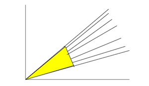
The graph will be extended to the vertex and glass plate sizes lying inside this area can be qualified for the pressure corresponding to the maximum pressure tested or in a simplified comparative analysis corresponding to the last design pressure curve graphed in the standard.
- When using ASTM E1300, the design pressure of an irregular shape glass unit (other than rectangular glass units) shall be that corresponding to the rectangular shape circumscribing the irregular shape. The design pressure of a rectangular glass unit is also applied to any irregular shape glass unit inscribed inside that rectangle. Please note this does not change the requirements of testing shapes to qualify shapes.

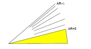
- When using ASTM E1300, aspect ratios greater than 5 can be approved provided that one specimen of the greatest aspect ratio and size is tested to the corresponding pressure in ASTM E1300 with an aspect ratio of 5. This corresponds to glass plate sizes that fall in the shaded area of the graph shown below. If approval of such aspect ratio sizes are sought these are to be considered when developing a test plan.
- When using ASTM E1300, unequal thickness in lights of laminated glass units can be determined by adding the two glass plate thickness' to select the appropriate "Glass Thickness Selection Chart" listed in table 5 of ASTM E1300. Use the lower performing of the two glass heat treatments to select the appropriate "Glass Type (GT) Factor" in Table 1 of ASTM E1300.
- When using ASTM E1300, unequal heat treatment in lights of laminated glass units, an aspect ratio greater than 5 can be approved provided that one specimen of the greatest aspect ratio and size is tested to the corresponding pressure in ASTM E1300 with an aspect ratio of 5. This corresponds to glass plate sizes that fall in the shaded area of the graph shown below. If approval of such aspect ratio sizes are sought these are to be considered when developing a test plan.

Specimen size requirement
The size of the specimen required to test glass blocks shall be 4' x 8' and built as specified in the South Florida Building Code. You can use 4' x 4' samples instead.
All sizes of glass block do not have to be tested. Miami-Dade County has allowed testing the largest glass block your company wishes to receive product approval for and smaller dimension glass blocks will be accepted for approval.
Exterior storage sheds have to be tested to the same PA201, PA202 and PA203 as habitable structures.
- All metal panels used on roofs and/or walls shall be tested in accordance with ASTM E-8 and a test report shall be submitted with the application.
Procedure for the approval of metal buildings
The following addresses how metal building panels (such as those used in storage sheds, hangers, etc.) shall be treated to comply with Miami-Dade County requirements.
First, metal-building companies shall test each of their panel configurations, and in order to be consistent, the following procedures are what this office has previously conveyed to the metal building industry with some minor clarification.
Two samples of each panel configuration must be verified to the requirements of Protocol TAS202, (Static air test). By testing two samples of each of the panel configurations for TAS202 in the largest girt spacing, design pressure values may be obtained that will give grounds for determining the weakest panel.
The results of the two samples of each configuration tested shall not vary more than 20%. The highest design pressure result of each of the two tests shall be dropped, and the lower design pressure value shall be used. The values of these panels are then compared with results of other panel configurations, and the determination of "the weakest" is made. Maximum allowable deflection is L/180 with a recovery at test load of 80%.
For example, if you have five panel configurations, (A, B, C, D & E), you shall test each of the ten following two panels wide samples to the static air tests described in TAS202.
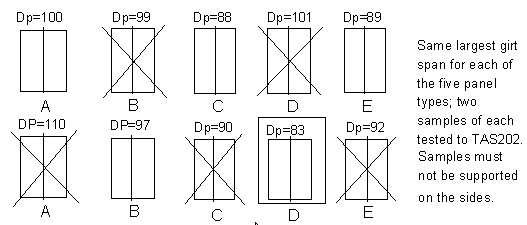
In this example, panel D with a design pressure of 83 psf was determined the weakest after dropping the highest values and comparing the remaining values.
Once you have determined the weakest panel configuration, based on the maximum fixed span tested above, an additional two samples of that same panel type shall be tested at the shortest girt span to the requirements of TAS202. The results of these two tests shall be within 20% and the higher result discarded.
The above mentioned procedure will allow you to interpolate design pressure values for spans between those tested, and limited by the pressures attributed to each tested unit.
From the example above the following applies:
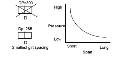
Secondly, the weakest determined panel from the testing above shall be subjected to the requirements of TAS201 and TAS203. Here, the largest girt span shall be tested, and shall comply with the three-specimen requirement. Testing these three samples will qualify shorter girt spacing for these impact requirements when staying between the boundaries set in the test results of TAS202.
The failure mode of the panels shall be cracks, or gaps greater than those allowed in the Florida Building Code for products that are to meet building envelope requirements. (This being the 1/16" x 5" gap through which air can pass.) Refer to question 51 for impact locations. The samples for this portion of the testing shall consist of three panels wide, and shall not be supported on the sides.
From all of the above testing, all the panels will receive the lowest resulting pressure value from TAS202 or of that panel determined "the weakest." If the manufacturer decides to rate each panel for its corresponding rating, the requirements are clear that three samples of that particular panel shall be additionally subjected to TAS201 and TAS203 and the shorter girt sample tested as well, and each one must obtain a separate Product Approval.
Up to three different fasteners may be qualified in this series of tests; one in each of the three samples tested for TAS201 and TAS203. If an additional fastener is to be qualified, an additional sample shall be tested to TAS201 and TAS203.
Thirdly, if planning to use the panels for roofing applications, the panels shall be treated separately. A different Product Approval Application must be filed for the roofing condition, where some of the above tests may serve some of these requirements.
The testing requirements for the roof are as required in TAS125 that can be obtained from the Building Code Compliance Office. A checklist for the roofing application of these panels is also available. Regardless if the panels are the same as the walls, the product approval must be kept separate since the requirements are different.
Procedure for the approval of metal frame structures that compliment other types of sheathing
A large number of questions have been directed to our department from the steel construction industry, regarding the fabrication of steel frame structures. These structures are not prefabricated, and they will be sheathed with sheathing material specifically prescribed in the Florida Building Code. We are therefore proposing the following to be carried out.
The procedure will be divided into two sections as follows:
The metal frame construction shall conform to all of the following:
- Shall have a special inspector at the site
- Shall have 5/8", 5 ply plywood sheathing minimum
- Shall have paper backed wire lath and stucco over the plywood
- Shall submit calculations to the building department from a Florida Registered structural engineer that includes all of the following:
- analysis of all structural members and their connections subject to live load, dead load, and wind load
- calculation of wind loads per ASCE 7
- overturning moments
- stress diagrams
- analysis of roof framing and necessary bracing
- analysis of member framing at wall openings under concentrated roof loads
- provisions for eccentric connections
- minimum connections per AISC Latest Edition J6 shall be 6000 lb. or per AISI cold-formed specifications unless approved by Product Control as an alternate method of construction
- stresses produced by dead and live loads shall not exceed the allowable stress no increase will be allowed.
- fabricated wall studs shall have continuous web members
- To be reviewed by the Department's certified structural plans examiner.
- Structural steel members shall have a G90 galvanization coating in accordance with ASTM A525 when less than 20 Ga.
- Cables and rods shall not be used for lateral bracing
- All structural metal shall be structural quality steel in accordance with ASTM A446
- All exterior doors, windows, shutters, plastic plumbing fixtures, glass blocks, roofing materials, etc. shall require to have Miami-Dade County Product Approval.
In addition to the above, this office strongly suggests:
- No further spacing of studs and trusses of more than 16" o.c.
- A truss load test following the procedures set by T.P.I.
- For positive and negative loads, a compression, transverse, and racking load per ASTM E72 should be performed on a wall section.
- All of the testing results of this section must be carefully evaluated.
All other sections of the Florida Building Code such as, but not limited to fire rating, and building distance separation shall apply.
Please note that this does not apply to metal sheathed buildings, screen enclosures, sheds and the like. Said structures require Product Approval prior to evaluating for permits as described in question 115.
The above requirements will provide the metal frame building industry the use of their alternate method of construction, as described in the Florida Building Code.
Types of approval for metal walls and metal roofs
The procedure below describes two types of roof or wall panel approvals. Different panel shapes or profiles will require separate application.
1) Approval for one profile and one gage based on only one span and one pressure in the field or interior zone, in the same manner as it was tested, and one maximum calculated pressure with reduced span in the corner and perimeter or end zone. Thicker gages of same profile can be included in the approval but they will be limited by the results of the thinner gage.
Minimum testing: Three specimens of the thinner gage, if several gages are to be included, for the maximum span to be used in the field or interior zone. The test result shall be within a 20% maximum difference to be accepted.
Calculations for one maximum projected pressure to be used on either corners and perimeter or end zone based on E, I and S adjusted by the test and limited by bending, deflection and reaction at fastener location.
Limitations: pressure and span on the field, corner and perimeter or interior and end zones can be reduced but size, profile, form, etc. of the panel cannot change.
2) Approval for one profile, one gage, several spans and pressures on the field, corners and perimeters or interior and end zones. Thicker gages of the same profile can be included in the approval but they will be limited by the results of the thinner gage.
Minimum testing: Three specimens of the thinner gage for maximum span to be used on all cases. The test result shall be within a 20% maximum difference to be accepted.
Calculations for pressures and spans based on E, I and S adjusted by the test and limited by bending, deflection and reaction at fastener location; producing one table or curve of load vs. span.
Verification: the maximum pressure shown on the curve or table has to be verified by a test of one specimen. If several curves are produced maximum pressure on each curve must be verified by a different test.
Notes:
- The testing procedure specified here applies to Uniform Air Static pressure only.
- Only tests that can verify the formula D= KwL4 / EI can be used with this procedure.
- Three test specimens are within the standards of the industry.
Requirements for the approval of combination window "systems" (Mullions)
Each of the windows to be used in the combination needs to first have Product Control Approval. Mullions, when pined on either end, as required in the code, will need to have a component approval. The County will accept rational analysis on this mullion where a combination using said mullion would be requested for tested. This single PA202 structural portion only test, will verify the rational analysis submitted. The mulled unit shall not be tested before submittal for product approval of the mullion. This supersedes question 96 in this document.
- For installations that require a mullion, the mullion has to be impacted.
Procedures for the different types of mullions (i.e. clipped mullions, unclipped mullions and side-by-side installations)
The initial procedure is as outlined in question 113 of this document. The following will provide some clear definitions and procedures when applying for this type of approval.
Definitions:
Clipped Mullion(s) - A member inserted between two window units which is supported at both ends by clips, brackets, pins, or any other direct mechanical fastening device.
- Clipped mullions will require having their own product approval. One cross sectional shape shall be applied to each submittal. i.e. Rectangular 1"x 2", 1"x 3", and 1"x 4" tubes may be qualified under one product approval submittal with a table or graph describing the properties of each. If steel is inserted in the mullion for strength, the steel shapes may be grouped. i.e. Different levels of I beams in a rectangular tube, or steel C channels. Each of these shapes shall require a separate product approval.
- Submittals shall be made based on rational analysis considering the E & I of the mullion only. The E & I of the adjacent window extrusions shall not be added to the calculations
- Drawings showing the mullion with the cross section of each window to be used with this mullion are to be provided. i.e. 1" x 4" rectangular tube with extrusion "A" on either side, 1"x 4" rectangular tube with extrusion "B" on either side, etc.
- Calculations for the end supports of the clipped mullion shall be provided.
- Structural Load tests shall be used on the sample instructed to test for submittal verification.
Unclipped Mullion(s) - A member inserted between two window units which serves as reinforcement to the window jambs. This member is not directly attached at the ends to the supporting structure.
- Unclipped mullions will require having their own product approval. Each of the jamb-unclipped mullion combination (i.e. 1" x 4" rectangular tube with extrusion "A", 1"x 4" rectangular tube with extrusion "B", etc.) shall require a separate product approval.
- Each different combination shall require a verification test to be determined by this office after submittal. The test shall include air, structural, and water test loads.
- Unclipped mullions may be analyzed in combination with the E & I of the adjacent window jambs. The total E & I may be used for the calculations.
Side-by side installation(s) - Two units that are arranged in a side-by-side configuration and are simply fastened at the jambs to one another. No reinforcement is added at the jambs to create this type of window combination.
- Side-by-side installations must be covered in the window product approval, and must be verified by the same tests of actual approval, or may be part of original submittal.
Approval of mullions with different loads and spans
The mullion shall receive an approval that will only serve to approve the pressure tested. Extrapolation will not be allowed in this case, and the mullion will be allowed for uses in shorter spans than that which was tested provided the tested pressure for the given application is not exceeded. The submittal shall be made showing what will be used in the testing, and this office shall verify the proposed testing before conducting the actual tests. (Regular procedure for mullion submittals to this office.)
There is no limit to the allowable maximum deflection for protection device systems when subjected to large missile impact as long as a build out is part of the approval, and all pertaining tests are performed. In this case, the approval will specify the required spacing away from the product being protected. Note that in the case of build out, lateral protection will be needed.
- When subjected to static air loading the maximum deflection of a shutter in the direction of the glass or object it is protecting when subject to static air pressure shall be no more that 2" or L/30, whichever is less. However, the minimum distance of the shutter to the glass or object it is protecting, when subject to static air pressure, shall in no case be less than 1".
- Roll-up shutters and accordion shutters do not have to be operable after testing, but they must be operable prior to testing. The whole system must be mounted, as it would be used in the field.
- In high rise buildings the loading criteria for protection devices must be capable of withstanding the appropriate loading per ASCE 7 while testing in accordance with the set protocols TAS201-94, TAS202-94 and TAS203-94 as applicable.
- Several manufacturers of storm panels who have identical production machines may apply for different product approvals relying on a common test. Manufacturers may enter into an agreement to apply for approval relying on a "common test." Each manufacturer upon application must reference the common test and provide a specimen for impact testing. Manufacturers under this agreement shall contact the Product Control Section to witness the production of each of the panels to be tested. Performing the testing procedure without prior notification and witnessing of fabrication by Miami-Dade will result in an invalid test for Product Approval.
- A poured concrete header may be used in lieu of concrete blocks for configuration #2 in Figure 1 of TAS201.
- Storm shutters (storm panels and accordions) may be tested with lateral supports. However, by testing with lateral supports, the approval will be limited to the width tested. By testing without lateral support the approval will have no width limit (width being the dimension perpendicular to the supported ends).
Storm panels
- For one storm panel model design, test 3 specimens, each consisting of 3 panels. Set up is as shown in the protocols where each specimen requires the mountings indicated.
- The failure criteria measurements for storm panels are taken after TAS201 and TAS203 tests are performed. The panels must not have a separation greater than L/180 or 1/2 inch; whichever is less. The length of the separation shall not be greater than 36 inches or 40% of the span; whichever is less.
- For testing an accordion shutter, the minimum width requirement is 3 feet provided the lateral sides are not anchored; however, be aware that the maximum anchoring distance this will allow approval for is 18" on center. If approval for greater anchoring intervals is desired, a wider span will be needed.
- To prevent the accordion shutter from 'closing' during testing, 'blocking' pins (pins, nails or screws) can be inserted on the top and bottom tracks.
- When testing an accordion shutter that is intended to be installed with center locking devices, the center locking device should be tested. At least one of the three specimens tested must include the center-locking device for the product to be approved.
Roll-up shutters
- The height requirement for testing on a roll-up shutter is seven feet.
- A roll-up shutter that can be installed in the field to roll inward or outward must be tested for both applications. It must be impacted for both applications; requiring an additional specimen.
- Comparative analysis will be allowed for storm bars when subjected to static air pressure. (See requirements contained in the shutter checklist)
- Storm bars on roll-up shutters have to be impacted.
Impact locations for storm panels
They are to be impacted as shown below.
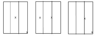
Large missile impact locations when testing to TAS201
See diagrams below.
No Straps or Bolts:

Single Strap or Bolts: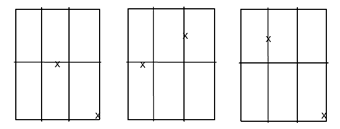
Multiple Straps or Bolts: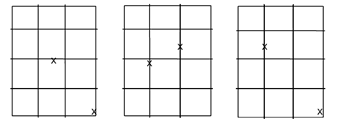
Impact locations for accordion shutters when the specimens are center locking
The impacts on accordion shutters shall be at the valleys. When a center lock is used the following figure shows the impact locations. (The "x" marks impacts to valleys, and when on the center locking strip the impact must be 2” below the lock.)

Shutter testing with an anchor that has not been issued an NOA
Approval can include the anchor tested, but the anchor can only be used for the installation of that particular shutter. If the anchor manufacturer applies for and obtains a component approval, all shutters meeting the load requirements of the anchor's component approval may use that anchor. Therefore, a shutter that was tested with anchor "X" may only be installed with anchor "X". Only if anchor "Y" has product approval will the above shutter be able to use anchor "Y"; provided anchor "Y" has equivalent or higher performance.
Required loading for skylights
Plastic +3xDesignP -2.0xDesignP
Glass+2xDesignP -2xDesignP
Required testing for a skylight that is being lined with a polycarbonate panel underneath the dome
In order to comply with Miami-Dade County Impact requirements:
First, you would test one skylight specimen to protocol TAS202, loading it to the required design pressure multiples. The air infiltration test is run first. The sequence for the pressure testing shall be the required pressures below or at design pressure, water at 15% of design, and ultimately the full test pressure. The specimen shall not fail any of these tests.
Second, you may use the specimen tested above as one of the three required specimens for TAS201 and TAS203. These must be impacted in two locations. These impacts shall be normal to the frame of the skylight and not to the dome. The large missile is allowed to penetrate the acrylic dome but must not penetrate or tear the interior polycarbonate barrier. Any tears evident to the interior barrier shall not exceed the dimensions of 5"x1/16" as specified. The three specimens are then cycled at the multiple design pressures intervals as specified in TAS 203 for glazed products. All three specimens must pass the above mentioned.
Third, one of the impacted specimens above shall be tested for water infiltration at 15% of its design pressure. No uncontrollable water penetration shall occur as specified in AAMA 101.
Testing solar collectors
- Three specimens are required.
- You only need to test the structural load pressure sequence in Protocol PA202. Attach the specimens as would be in the field and apply the corresponding pressures.
- PA201 and PA203 are not required.
Required tests for sunshades
If the shade is canvas, then it must meet the 75-mph wind requirements per South Florida Building Code. If the shade is rigid, it must comply with TAS202.
How sun shades are handled under ASCE 7-88 and Impact Testing
A structural load test per TAS202 will have to be performed, where the applicable pressures are to those of ASCE 7 based on 75 miles per hour.
Also, a permanent label shall be affixed to the sun shades approved that reads the following:
WARNING: THIS IS NOT AN APPROVED HURRICANE PROTECTION DEVICE. DURING A HURRICANE THIS PRODUCT MAY BECOME A HAZARD AND IT MUST BE REMOVED AND STORED IN A SAFE PLACE.
Please note that this category of products will still require a product approval in order to be used in Miami-Dade County.
Required testing for sun shade awnings to comply with ASCE 7
First, the awning needs to be tested to TAS202 only. The three required samples may be tested on wood and shall be attached along the top and at the single lateral support. The awning needs to be pressurized and the following method of attachment to the wood shall be followed.
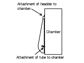
Note that the awning may not be supported other than the particular design of the awning. Alternate procedures can be presented to the Building Code Compliance Office in the form of a proposal.
Meeting the new requirements of PA201, PA202, and PA203
The following depicts how that may be accomplished.
First, the importance factor to be used when designing to ASCE 7-88 is 1.05. The walk-in coolers need to be tested for impact and cyclic loading, where the cyclic loading has corresponding structural design load multiples. If your design incorporates a roof design or material type that is covered in the Miami-Dade County Roofing protocols, it would have to be tested under that protocol. Also, a live load test may also be required per section 2314.2 of the South Florida Building Code.
Second, the following depicts some of the configurations that would be required in order to comply with the established requirements.
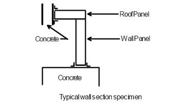
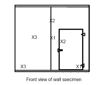
The depicted X1, X2 and X3 correspond to the two impact locations of each of the three wall specimens required.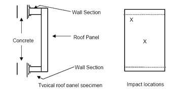
The X depicts the location of the two required impact locations on each of the three roof specimens required.Comparative analysis for windows
Comparative analysis is acceptable for windows, provided the largest window manufactured is tested. All smaller windows having the same system can be approved through comparative analysis and always complying with FBC Sections 2411.3.2.5 and .6. This normally applies to non-impact resistant windows, for impact windows the highest pressures obtained through comparative analysis may not exceed the cycled pressure tested.
Single hung window impact testing for large missile approval
Single hung windows shall be impacted two times as shown below for each required specimen.
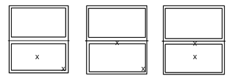
Double hung window impact testing for large missile approval
Double hung windows shall be impacted:
Two times as shown below for each required specimen.

Testing specimens for the same series of windows using different mounting conditions
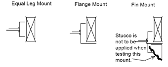
You may test one specimen of each of the above shown configurations to comply with the three specimens required. Also, keep in mind that the fastening system used to anchor the window for the test is the anchoring system that will be approved for each of the configurations shown. These anchoring systems must be specified in the set of approved drawings of the window, and verified by the certified laboratory conducting the test.
Minimum amount of testing required in order to qualify all the different glass if not qualifying for impact
For example, if all your extrusions are the same, and you provide a 1/8", 3/16" and 1/4" annealed glass thickness, the following is what you can do to qualify the window line.
First, test three specimens using the thickest glass for air infiltration, 1/2 test load, design load, water at the maximum that the extrusion will take (this should be to the corresponding pressure of the highest design pressure obtained among all the different glass thickness), full test pressure and forced entry.
Second, you may test the specimen of 3/16" glass for structural loads only.
Third, you may test the 1/8" glass specimen for structural loads only. Keep in mind that the maximum design pressure obtained from these two last series of tests must fall in range for the corresponding water test performed in the 1/4" glass. The following is the resultant testing.

Note that the only thing that can change is the thickness of glass or type of glass.The glass type/thickness of windows when comparative analysis is used
The glass standard ASTM E1300 is the criteria to be used when designing the window and obtaining the minimum glass thickness to be used on a particular glass area. This standard, however, is not the only criteria to be used when downsizing a window to change the glass type or thickness without performing the required tests.
Using a picture window as a simple example, the following will apply:
First, one type of extrusion, and glazing method/system is used to qualify this window; if components of the window system change, (other than the glass type / glass thickness) then the product shall be treated under a separate product approval.
With respect to the testing for non-impact windows, TAS 201 and TAS 203 do not apply. Only TAS 202 will be used. Test three samples of the largest size window with the required glass thickness per the ASTM E1300 standard, to the requirements of TAS 202.
Since in this example the unit is a fixed window, these units do not need to undergo the forced entry requirements. If it were an operable unit, all three units must be tested for forced entry also. These three samples will qualify this maximum size window with the glass tested.
The test sequence in TAS202 for testing a casement window which has three separate locks that are not activated by single action hardware
First, engage all locks and perform the air infiltration test.
Second, disengage all locks and only engage the center-most (main) lock. Perform the 75-mph load test and water test as described in TAS202.
Third, engage the other two locks and perform the remaining procedures in TAS202. Forced entry resistance test (F.E.R.) shall be done with all locks engaged.
If a light on the unit breaks while conducting the test loads
You can re-glaze the light on the same specimen and perform the following structural loads: 1/2 test load, design load and test load (both positive and negative). Note, the re-glazing procedure will be allowed as many times as there are lights on the specimen, but in no case shall any light be replaced more than once on a given specimen.
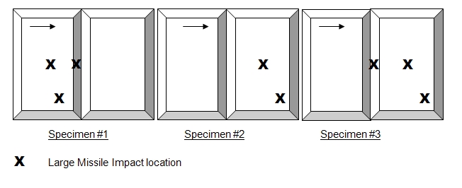
Impact locations on a horizontal sliding window
They are basically the same as the locations on a sliding glass door. See below.

Board and Code Administration Division
Jaime D. Gascon
Herbert S. Saffir Permitting and Inspection Center
11805 SW 26 Street,
Room 124
Miami, FL 33175
311

